

The Stopping Power: Essential Heavy-Duty Truck Brake Components and Their Functions
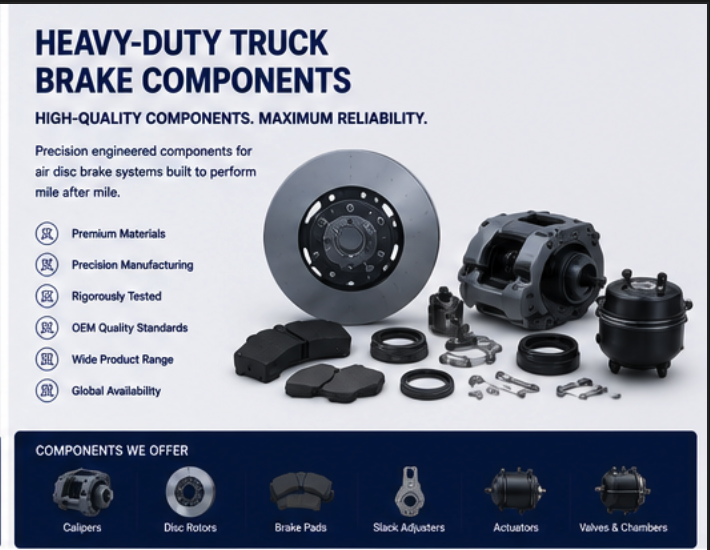
A heavy-duty truck brake system is not a single device but a network of components working in perfect synchronization. From the air compressor that generates power to the friction material that contacts the rotor, every Heavy-Duty Truck Brake Components has a specific function. Understanding these parts helps drivers, mechanics, and fleet managers maintain safe vehicles. These components are the building blocks of Pneumatic Brake Actuation Systems, which use compressed air to transmit force from the driver's foot to the wheels.
The Air Supply System
Before any braking can occur, compressed air must be generated and stored.
1. Air Compressor:
-
Function: Draws in atmospheric air and compresses it (typically 120-150 psi).
-
Location: Engine-driven (gear or belt), mounted on the engine.
-
Type: Single or two-cylinder reciprocating piston.
-
Cooling: Water-cooled or air-cooled (using engine coolant or fins).
-
Duty cycle: Up to 100% (can run continuously).
-
Common failures: Worn piston rings, faulty unloader valve, oil carryover.
2. Air Governor:
-
Function: Controls compressor operation. Unloads compressor when system pressure reaches cut-out (e.g., 130 psi); loads when pressure drops to cut-in (e.g., 105 psi).
-
Location: Mounted on or near compressor.
3. Air Dryer:
-
Function: Removes moisture and oil vapor from compressed air. Prevents freezing in cold weather and corrosion in air system components.
-
Desiccant: Silica gel beads that absorb moisture.
-
Purge valve: Expels collected moisture periodically.
-
Heater (optional): Prevents freeze-up in cold climates.
-
Service interval: Replace desiccant cartridge annually.
4. Reservoirs (Air Tanks):
-
Function: Store compressed air for instant use.
-
Typical truck: 4-6 tanks, total capacity 20-40 gallons.
-
Types: Supply tank (first in line), primary tank (front brakes), secondary tank (rear brakes), auxiliary tank (accessories).
-
Drain valves: Manual or automatic; used to expel accumulated moisture.
5. Safety Valve:
-
Function: Releases air if system pressure exceeds safe limit (e.g., 150 psi). Protects against compressor governor failure.
-
Location: On supply tank.
The Brake Control System
These components translate driver intent into air pressure signals.
6. Foot Valve (Treadle Valve):
-
Function: Driver interface. Position of the pedal determines output pressure.
-
Operation: Dual-circuit (two independent output ports for safety). Depressing the pedal opens valves, sending air to relay valves.
-
Pedal feel: Progressive (more pedal = more pressure).
7. Relay Valve:
-
Function: Delivers air to brake chambers near the wheels, reducing delay between pedal application and brake actuation.
-
Location: Mounted near the axles they serve.
-
Control signal: Small air pressure from foot valve.
-
Supply: Large air line from reservoir.
8. Quick Release Valve:
-
Function: Rapidly exhausts air from brake chambers when the brake is released.
-
Location: Near the brake chambers.
9. ABS Modulator Valves:
-
Function: Rapidly cycles air pressure to prevent wheel lockup during hard braking.
-
Operation: Electronically controlled by ABS computer.
10. Parking/Emergency Control Valve (Dash Valve):
-
Function: Driver control for spring brakes (parking brake). Pull out to release; push in to apply.
-
Location: Dashboard, driver's side.
The Brake Actuation System
These components convert air pressure into mechanical force.
11. Brake Chamber (Air Cylinder):
-
Function: Converts air pressure into pushrod force.
-
Operation: Air enters chamber, pushing a diaphragm and pressure plate, which extends the pushrod.
-
Types:
| Type | Use | Characteristics |
|---|---|---|
| Service chamber | Service brakes (foot pedal) | Single diaphragm |
| Spring brake chamber | Parking and emergency | Two chambers (service + spring) |
| Tapered (pancake) | Low-profile applications | Shorter, wider | -
Stroke: Pushrod travel (typical 1.5-2.5 inches at full application). Excessive stroke indicates wear.
12. Automatic Slack Adjuster:
-
Function: Transfers force from the pushrod to the camshaft (or caliper). Automatically maintains proper pad-to-rotor clearance.
-
Type: Clear-sensing (most common), stroke-sensing.
-
Operation: Internal ratcheting mechanism compensates for pad wear.
-
Inspection: Pushrod stroke should be within specification (e.g., 1.5 inches at 90 psi). If stroke is excessive, adjuster may be seized.
13. Camshaft (S-Cam) – Drum Brakes:
-
Function: Rotates to force brake shoes against the drum. Used on drum brake axles (older).
-
Bushings: Bronze or plastic; wear leads to poor brake geometry.
14. Caliper (Air Disc Brakes):
-
Function: Holds brake pads and applies clamping force to the rotor.
-
Type: Fixed (pistons on both sides) or sliding (pistons on one side).
-
Slides: Lubricated pins that allow caliper to center on rotor. Seized slides cause uneven pad wear.
The Friction Components
These parts convert motion into heat.
15. Brake Pads:
-
Function: Friction material that contacts the rotor.
-
Material: Semi-metallic (most common), ceramic, organic.
-
Wear indicator: Squealer tab (metal tab contacts rotor when pads are worn) or electronic sensor.
-
Minimum thickness: Typically 1/4 inch (6 mm) at the thinnest point.
16. Rotor (Disc):
-
Function: Rotating friction surface attached to the wheel hub.
-
Type: Solid, ventilated, slotted, or drilled.
-
Wear limit: Minimum thickness specification (stamped on rotor hat). Replace if below minimum or cracked.
The Parking/Emergency System (Spring Brakes)
Spring brakes are a critical safety feature.
17. Spring Brake Chamber:
-
Function: Combines service brake chamber and parking/emergency chamber.
-
Service section: Normal air-actuated brake.
-
Spring section: Powerful spring that applies the brake when air pressure is low (spring brakes are "applied by spring, released by air").
-
Caging bolt: Allows manual release of spring brake (for towing).
18. Spring Brake Control Valve (Dash Valve):
-
Function: Driver control for spring brakes. Pull out to release; push in to apply.
Maintenance Best Practices
-
Drain air tanks daily: Prevents moisture from corroding components.
-
Check brake stroke: Measure pushrod travel with brakes fully applied. Adjust if out of specification.
-
Inspect pads and rotors: Measure pad thickness; check rotor for cracks.
-
Grease slack adjusters: Use specified grease; lubricate every 50,000 miles.
-
Replace air dryer filter annually: Prevents moisture contamination.
-
Check for air leaks: Listen for hissing; use soapy water to identify leaks.
-
Test spring brakes: Apply parking brake on a slight grade; vehicle should hold.
Common Failure Modes
| Failure | Cause | Symptom |
|---|---|---|
| Brake drag (pads contact rotor constantly) | Seized caliper slides, failed slack adjuster | Excessive heat, brake pull, reduced fuel economy |
| Brake pull (vehicle pulls to one side) | Contaminated pads, frozen caliper, air line restriction | Steering correction needed when braking |
| Low air pressure alarm | Compressor failure, air leak, governor failure | Warning light/buzzer, spring brakes may apply |
| Long brake pedal travel | Excessive pushrod stroke (needs adjustment) | Driver must push pedal farther |
| No spring brake release | No air pressure, failed dash valve, caged spring | Parking brake will not release |
Conclusion
Every time a heavy truck stops safely, dozens of Heavy-Duty Truck Brake Components work in perfect harmony. From the air compressor that generates power to the brake pads that create friction, each part is essential. Pneumatic Brake Actuation Systems are reliable, but they require regular maintenance. Understanding these components empowers drivers and mechanics to identify problems before they cause failures.